Lesson 11 in this program will show the drawing student the purpose of maintaining proper proportion ratios, as it regards to placing the figure into perspective. This will be a drawing lesson, so get out your sketchbooks.
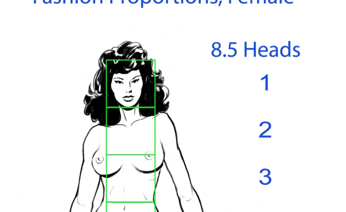
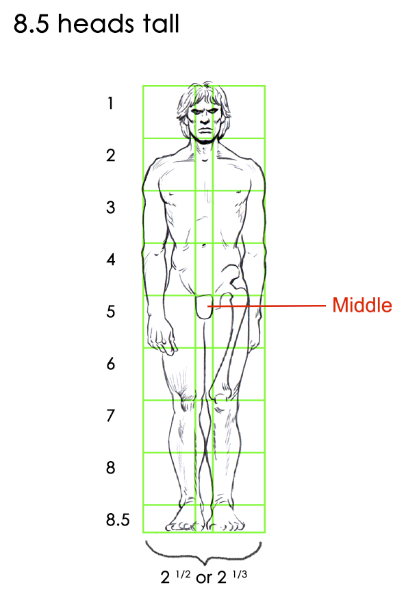
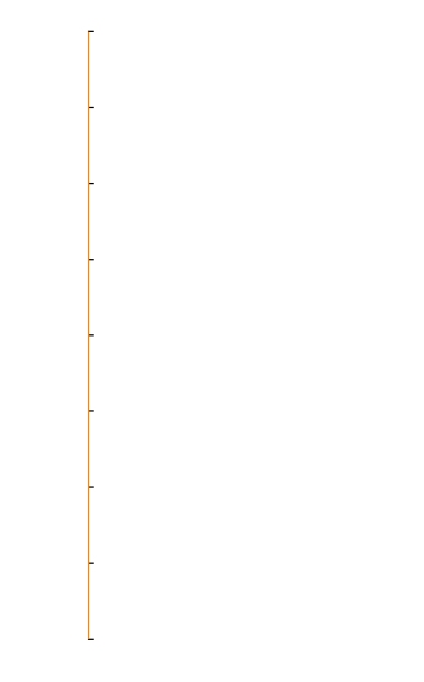
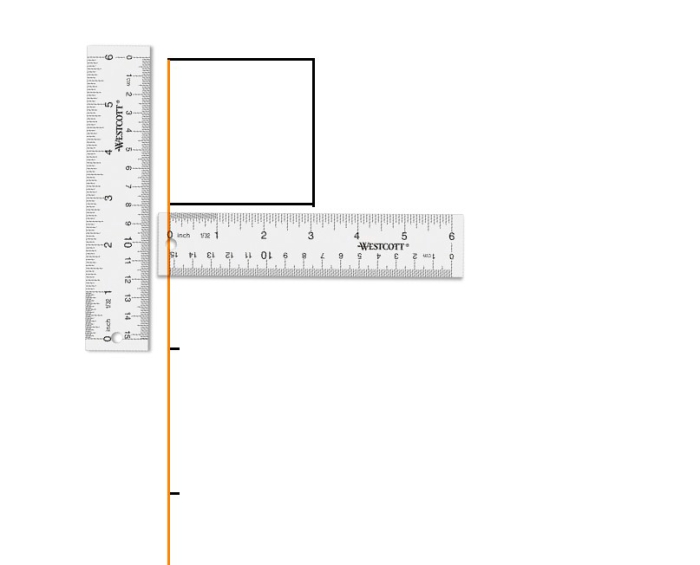
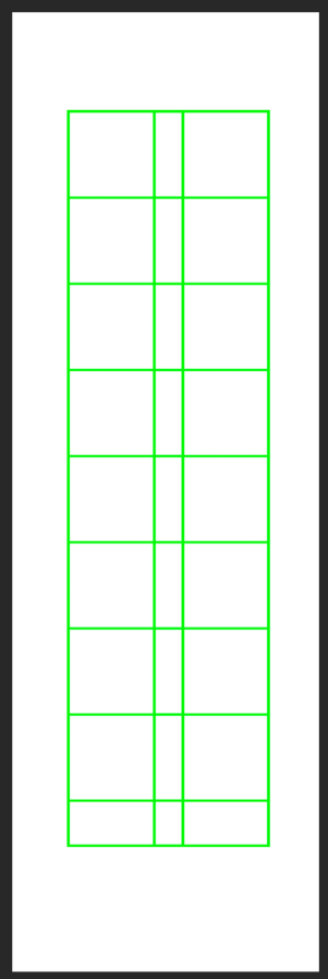
As a preliminary exercise, set up an 8.5 head Flat Diagram Map, like this. You can do it on a small piece of paper, which you can cut out, or on a larger page. This is the base work for the final drawing, so I always use a separate page for the ‘working parts’. If you are doing it on one big paper, organize your page landscape format, and draw this Diagram Map in the upper left corner- not in the middle. (since this is not the real drawing you are doing, it is the helper) Here is the Flat Diagram Map.
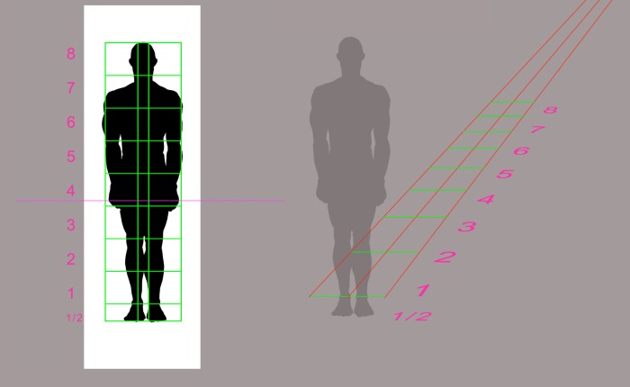
Andrew Loomis is going to show us the beginning steps regarding how to ‘project’ the figure onto the ground plane. As a good teacher does, he has isolated the figure projection to regard only the flat placement of the figure’s silhouette onto the ground. This is the primary step for being able to draw the full 3-dimensional figure in perspective, using foreshortening.
For now, we will be working with the flat, 2-d figure like this.
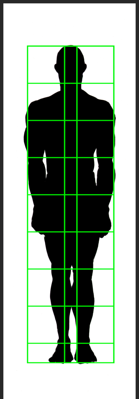
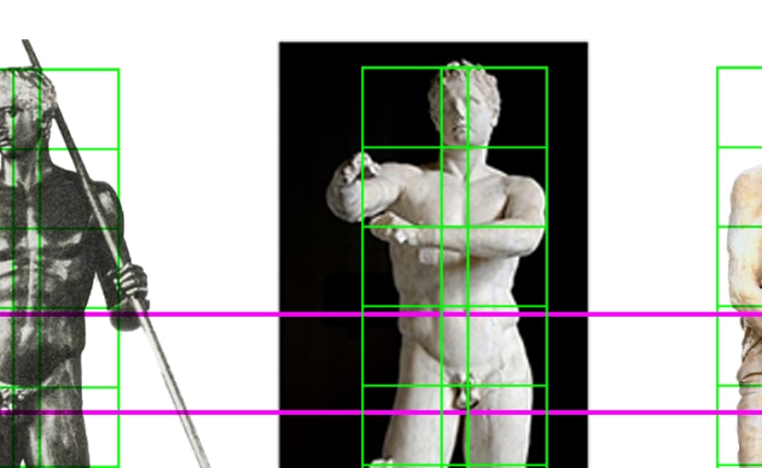
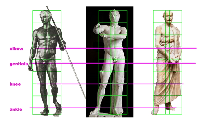
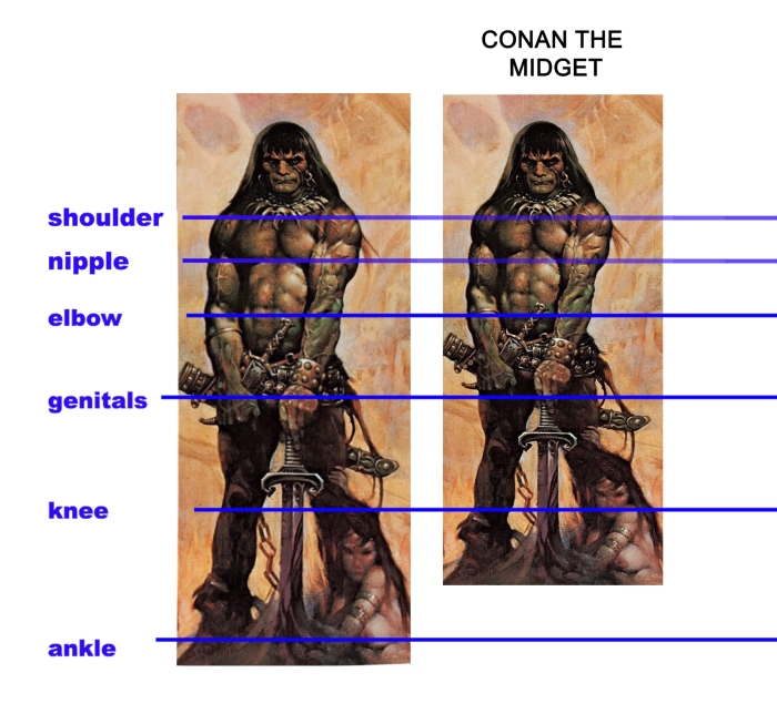
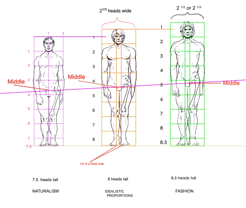
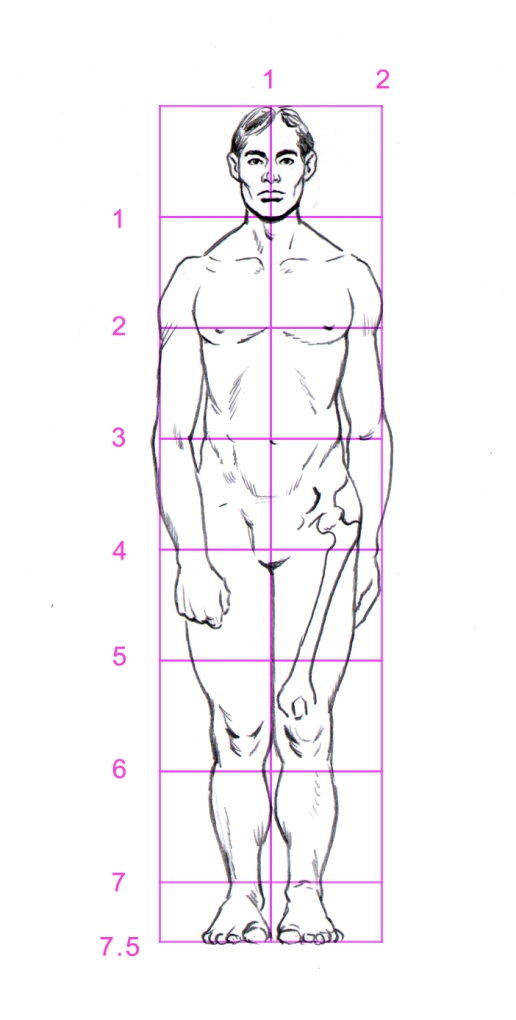
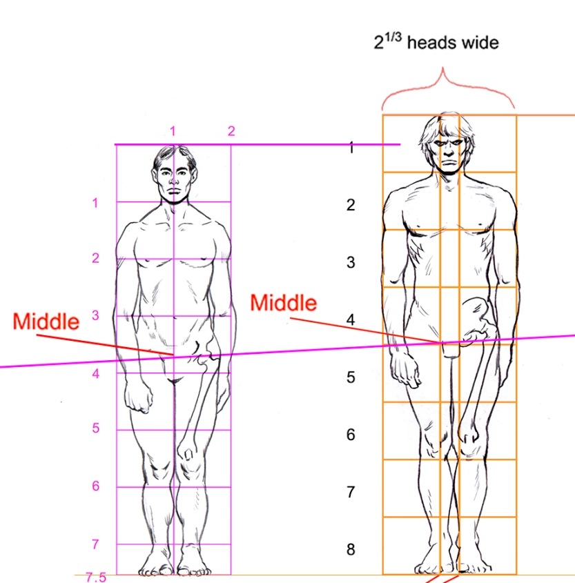
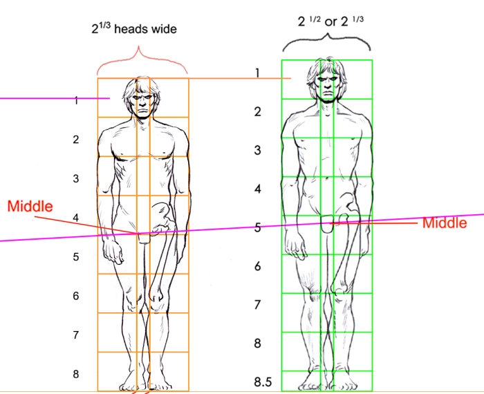
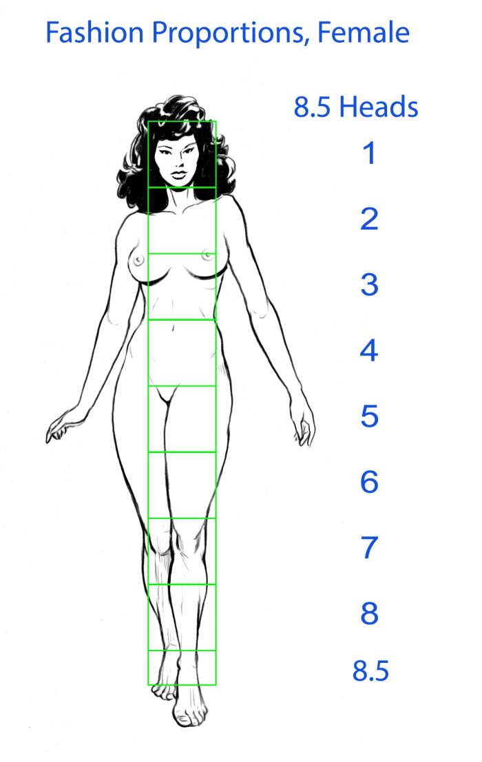
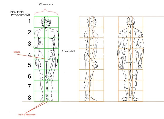
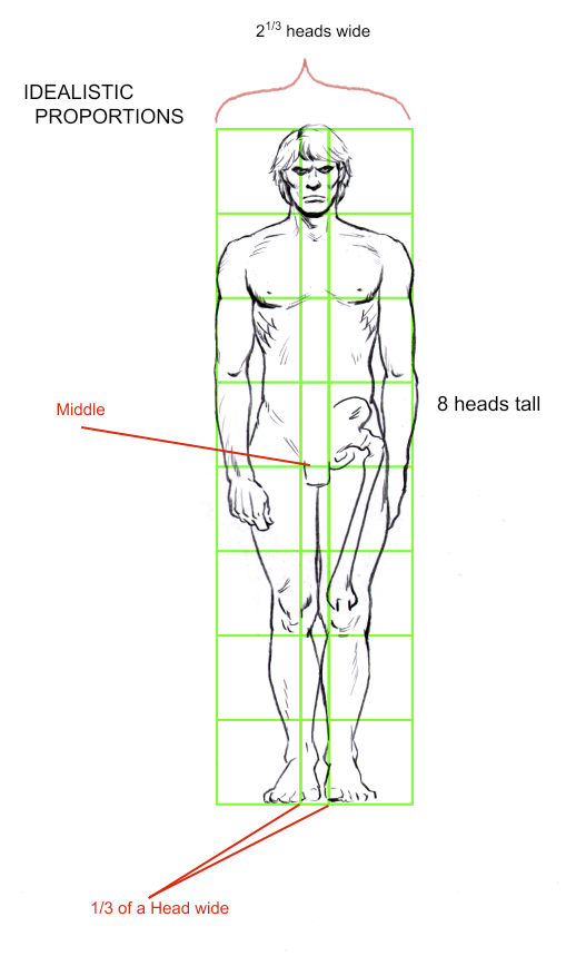
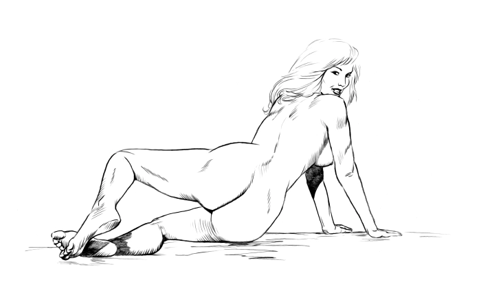
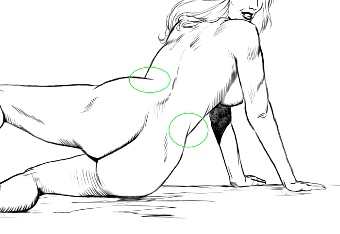
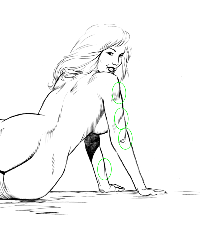
Go ahead and set up an 8.5 head proportion figure in silhouette. Make sure all the anatomical parts hit where I have drawn them. To help, I will add a drawing with the anatomy drawn in so you can properly place the parts. It is hard to do with just an outline. Do not try to draw the body parts though. Use my details to help you locate where your outline drawing ‘parts’ will land. This is for reference. 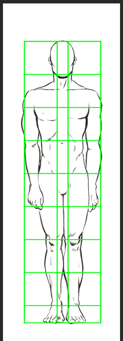
Again, don’t place your figure or the Flat Diagram Map smack in the centre of your paper. Put it off to one side, and in the upper corner. We are going to be using a lot of paper real-estate for this drawing.
You do not need to draw the colours.
- Figure & horizon
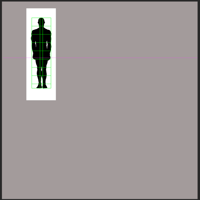
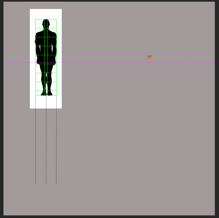
Now, once you have your figure drawn, somewhere not in the centre of the drawing, establish a Horizon Line for the actual assignment of projecting the 2-D figure into perspective. Here I have drawn the Horizon Line with a pink line.
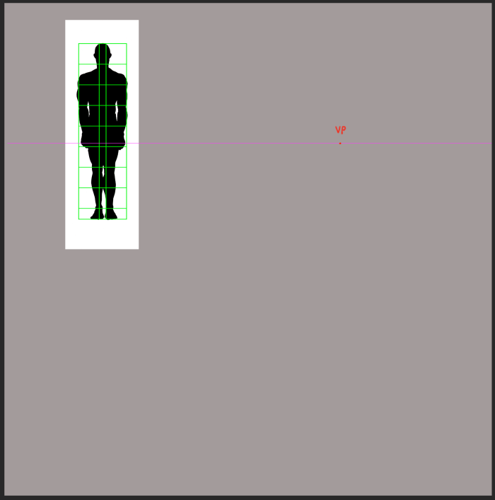
2. Pick a Vanishing Point
Next, pick a place on the line. This will be the vanishing point. All the straight lines will coalesce to this point. You may choose any place on the Horizon for this point. Mine is in red below.
3. Cast verticals
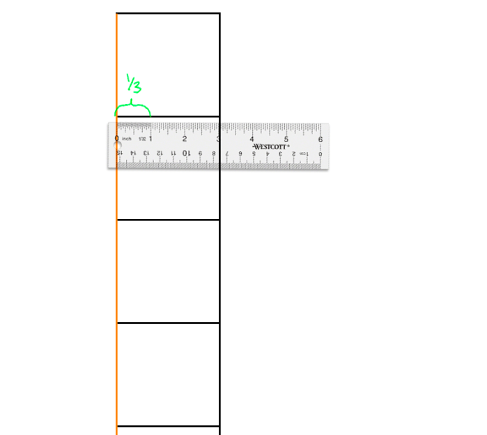
Now, from the outer corners of your Flat Diagram Map, (in green) project two vertical lines. Also, add a third from the centre, all dropping down. You may draw the line as far as you like, but each of the lines must be the exact same length. The length you draw the lines determines the steepness of the plane you are envisioning for your drawing. The further you go, the steeper the plane will be.
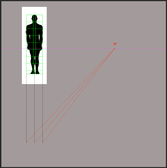
4. Cast to V.P.
Now, from the termination point of your 3 verticals, draw 3 lines, all meeting at the Vanishing Point (VP) you drew in step 3.
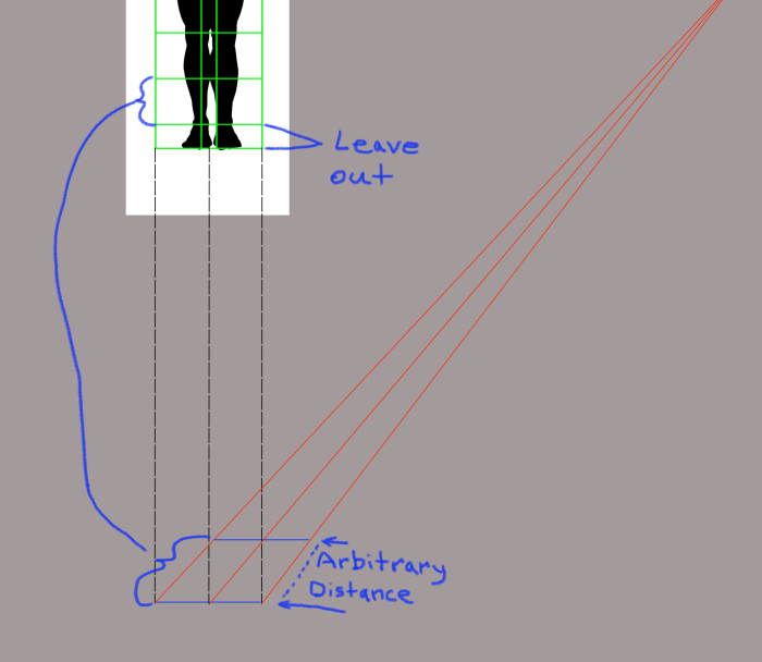
5. Set The Primary Unit
Now, at an arbitrary depth, set to your eye’s taste, the horizontal crossing point which will establish the 1st ‘head-size unit’, called the Primary Unit. The larger you make the depth of the Primary Unit, the more the figure will be stretched out. This will describe many things which you as the artist may choose, such at the relative distance we as viewers are standing relative to the VP. For now, choose a horizontal cross point which looks good to you. It doesn’t matter for this assignment.
Also of note, this Primary Unit you are drawing will omit the additional 1/2 of a head which is reserved for the ankle to sole of the foot measurement. We will account for this later.
6. Designate the Line Names
To refer to them, we will call the 3 lines of perspective, lines a, b and c. This is for instructional purposes, and you don’t need to label yours.
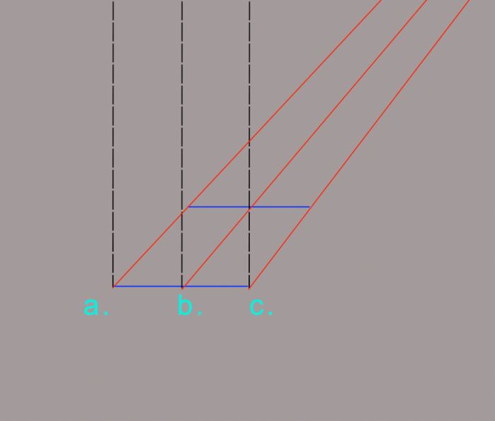
7. Point D
The place where your first depth horizontal line (presented in blue below), crosses the central red line of perspective (we call this, line B) is an important new point.
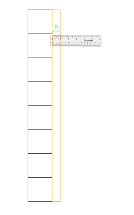
This crossing point of red and blue lines will be labeled as Point D. Point D is very important, because now you will know how to define all of the remaining unit horizontals, as they move away in the distance. Draw a line from Point A through Point D, terminating somewhere on line C (drawn in green). Where the new diagonal (green) line terminates on line C is our next point.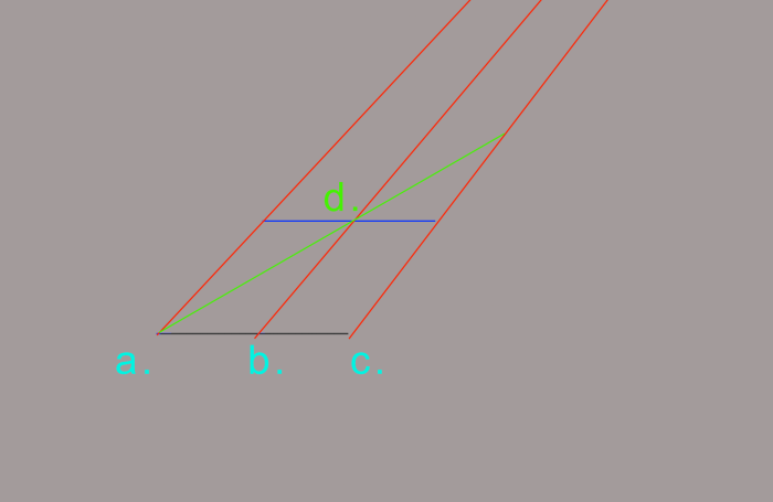
8. Point E
You guessed it. The new point is called Point E. This is where you draw the second depth point of the next head unit. The diagonal line we just drew establishes the depth of where the units in perspective will fall. There is no other way to do this. Learn to do this well at this stage, because it will help you immensely in the future. Do not rely on Photoshop distortion and reshaping tools. You can’t get it right by eye. You must learn how to do this mathematically, in order to be convincing.

9. Repeat for F and G
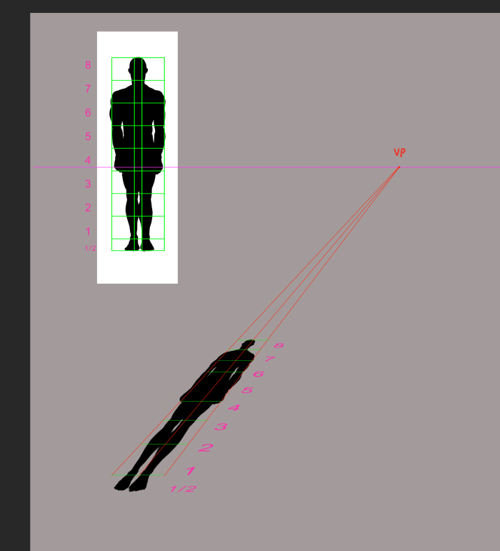
This is the process for each new unit. Continue with points F and G (pink) , drawing diagonally (cyan) then horizontally (pink again) I have faded the completed points and lines for clarity.
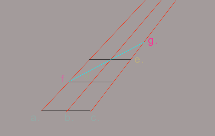
10. Repeat until 8 units are drawn.

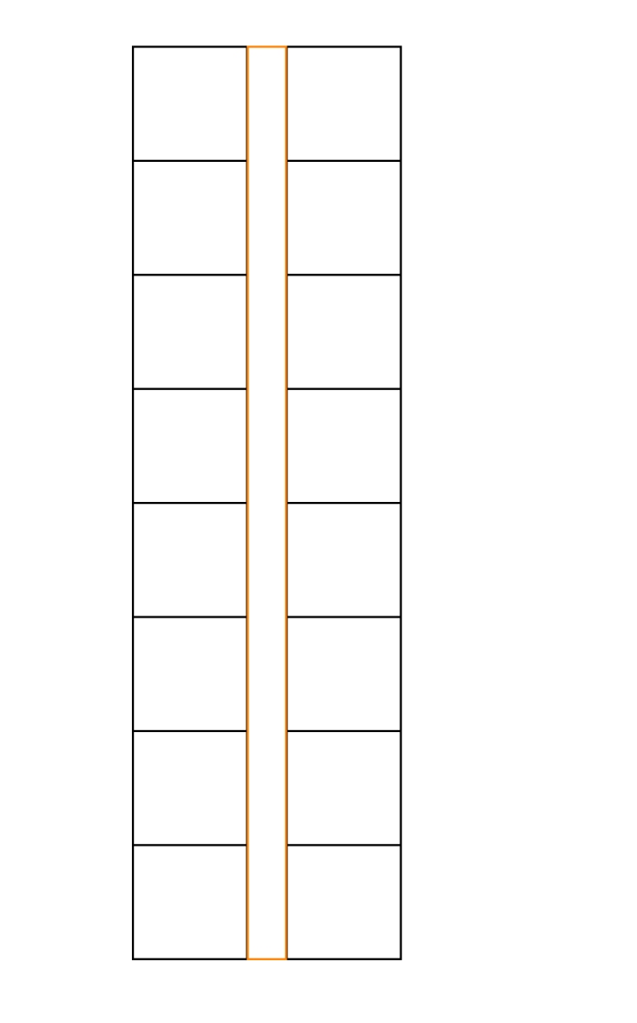
11. This is the Flat Diagram Map projected onto the ground, at the perspective you chose. Notice that the bottom 1/2 square is not represented as we mentioned in Step 5 above. This is because we needed to project the distance of a single, full unit to start. 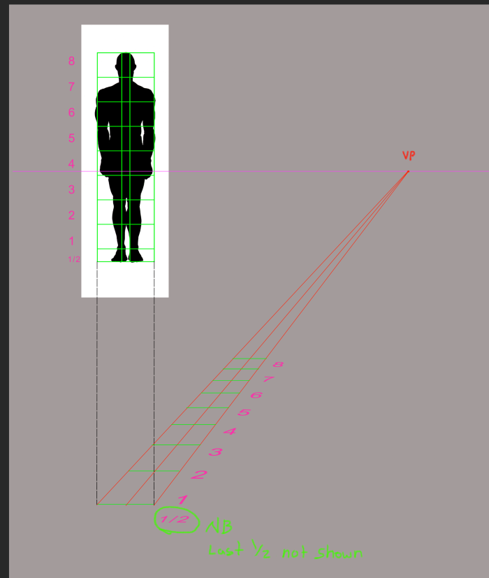
12. Now we will transfer our drawing using the Flat Diagram Map. The crosspoints will show us where the anatomy will line up. As a fun little demonstration, I want to show how it is virtually impossible to predict the way the flat outline- the shadow more or less- will look at a given perspective. For fun, I have placed the flat figure (not in perspective) at the foot of our projections. Take a look, and see how you imagine the shadow of the figure would lay, with the given steepness of the plane and unit size of head. This is to show how guessing with Photoshop distortion will not work.
Take a guess:
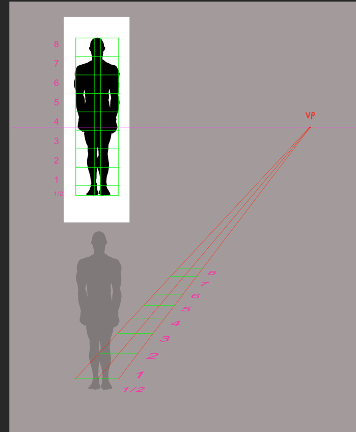
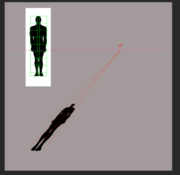
13. The Flat Diagram in Perspective
This is how a 2-d cut out of a figure would appear on the given plane and unit head size choice depth we made.
The parts of the anatomy land where the corresponding cross lines in the Flat Diagram Map in the front view shows. It would be near-impossible to guess this. I find it constantly surprising when I work it out. Did you imagine it to look this way, even with the map line projected on the ground?
Following this simple exercise, we will learn how to use the same principles to determine cast shadows, foreshortened figures and the human figure in perspective.
Thanks for reading. I hope to see you next week.