Variable Perspectival Spaces within a Single Block

On page 43 of Successful Drawing, Andrew Loomis shows a very useful mechanic for artists to know in order to convincingly draw architectural details or features on mechanical objects in perspective.  This example demonstrates how to project a sequence of repeating sections, found within a whole, using a vertical and a horizontal scale. This is similar to previous lessons, but it expands the skill set so that the artist can draw repeating sections which are varied in sequence.  For example, imagine a condominium building in perspective.  The viewer can see the front of the building going off down the block.  This viewed side features a set of 4 windows, followed by  a portico with a double entryway in the middle, then another set of 4 windows.  Each of the openings of the windows need to be identical in size; but naturally, of a different dimension than the portico, which again is different than the two sets of double doors within.  This then is an example of Variable Perspective Space, Within a Single Block.

Let us begin.

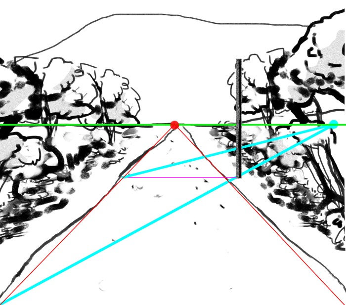
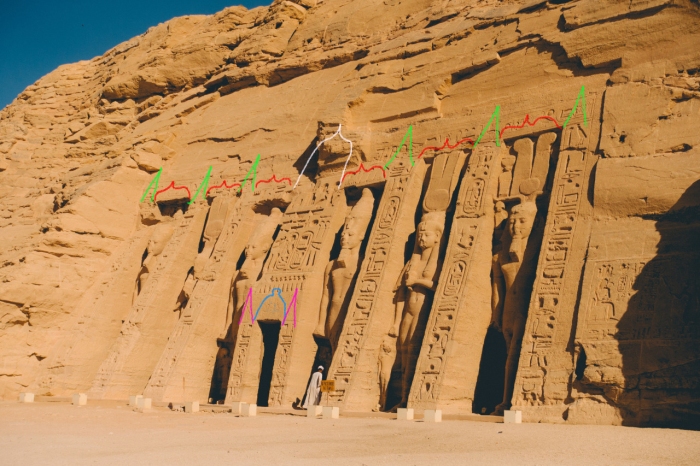
Suppose you are an illustrator, and you are asked to draw the Egyptian temples at Abu Simbel.  Let us say that you are drawing the small temple, and you have (for whatever reason) a restriction as to the perspective you must use.  You search through the internet for reference, and let us say that there is nothing in the correct perspective which you need.  Short of traveling to Nubia, you cannot get a reference shot of the correct perspective.  This is how it is done.

Here is the small temple at Abu Simbeltumblr_nrqdlqhwMT1tkairwo1_1280

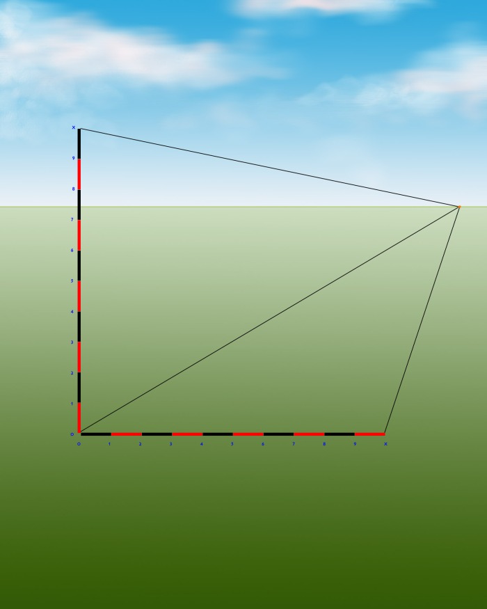
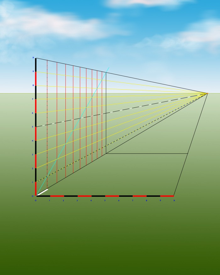
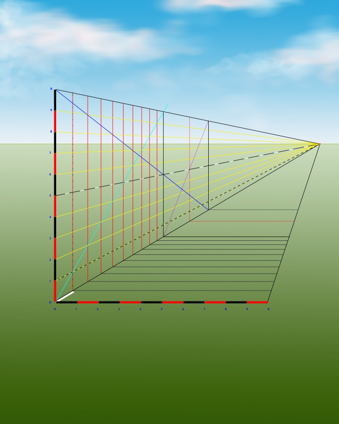
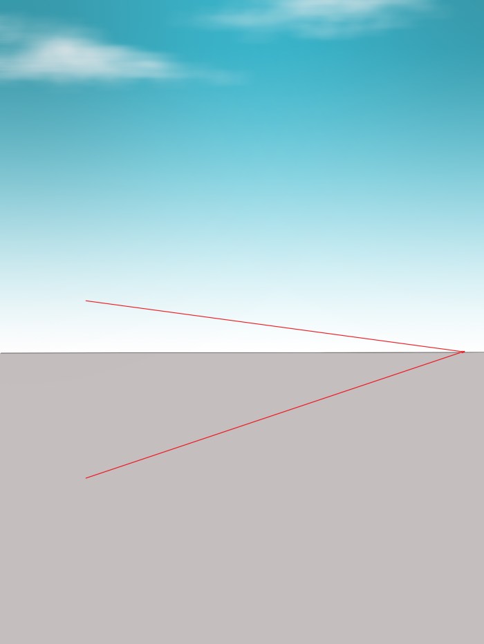
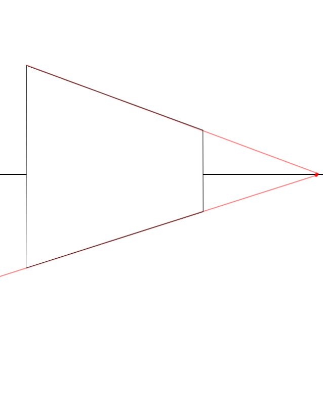
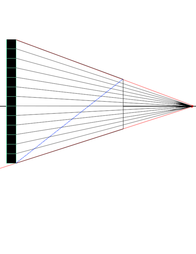
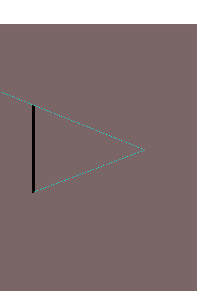
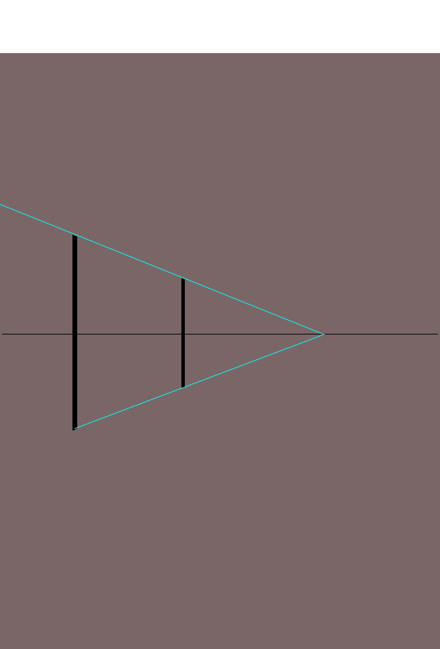
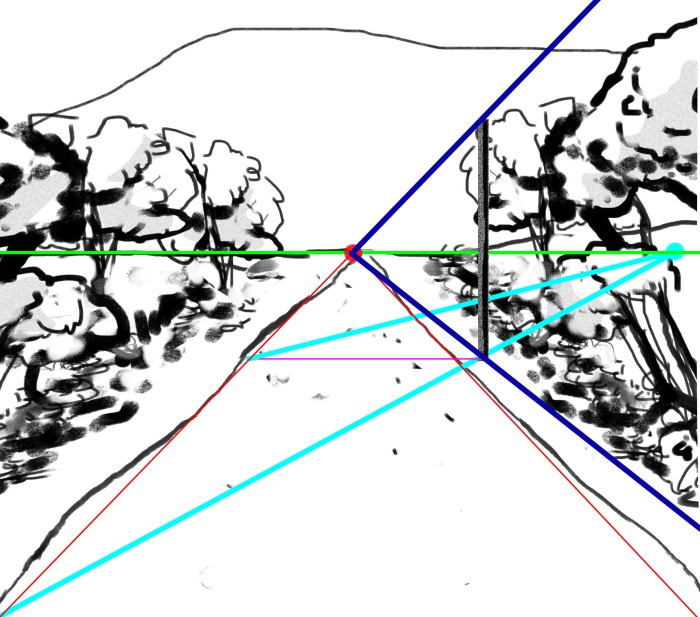
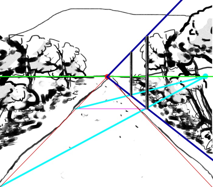
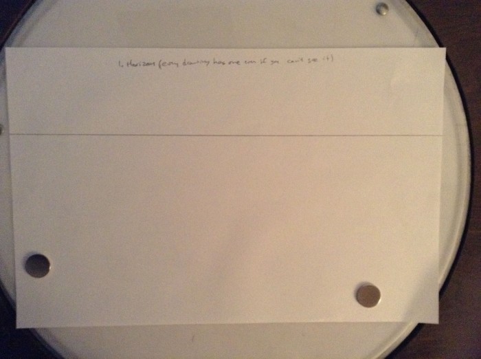
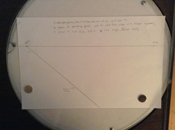
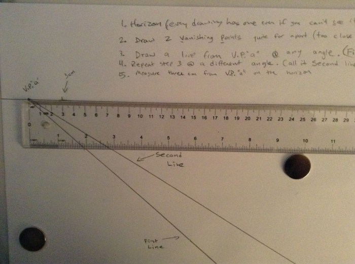
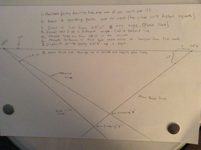
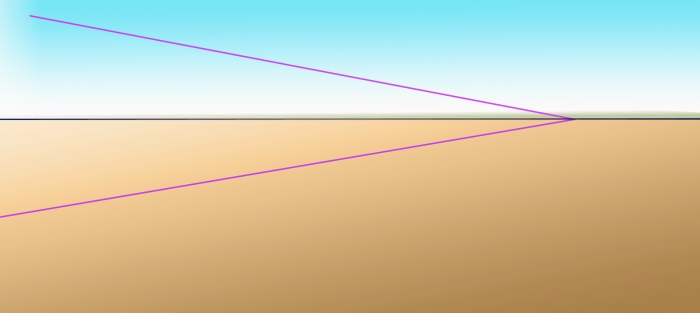
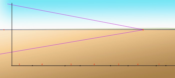
  1. Lay out the image in the angle you want, establishing the horizon and the perspective which you need to draw the site at.  This can be done with any angle of perspective that you wish.  2
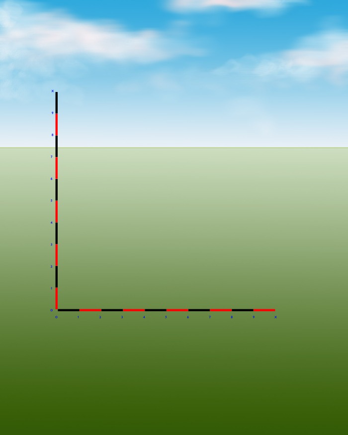
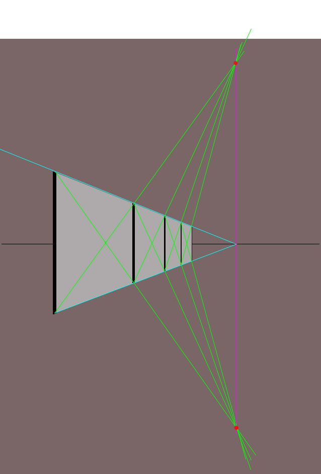
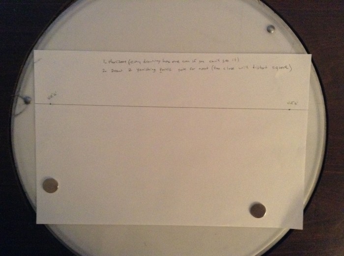
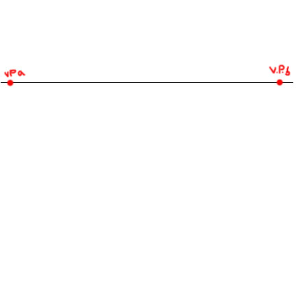
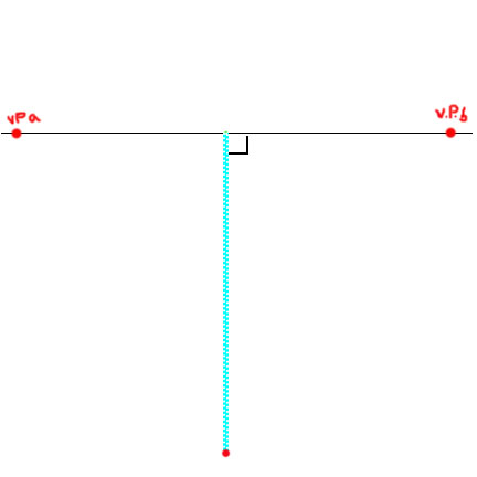
  2. At the wide edge, establish the vertical and horizontal planes which will be used as your measuring lines.  (see last posting for further use of the horizontal and vertical lines as measurement guides)3
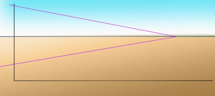
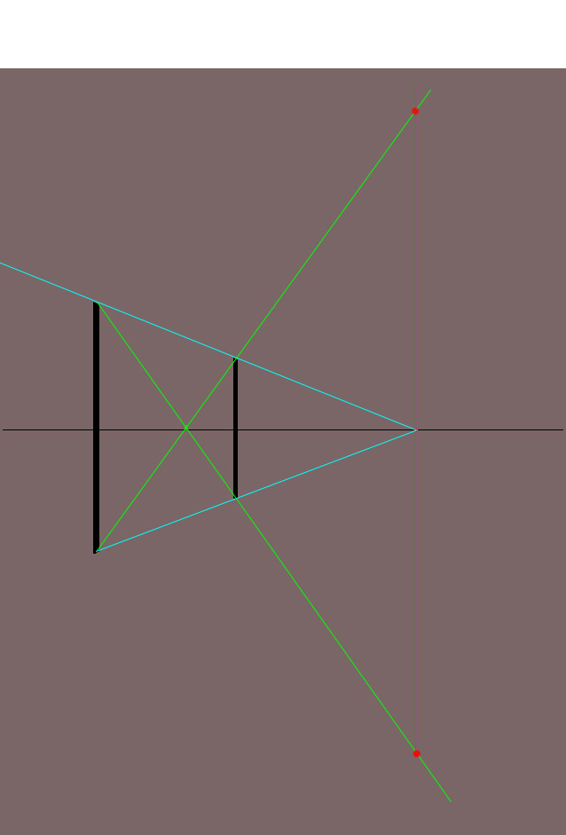
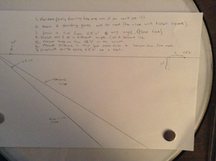
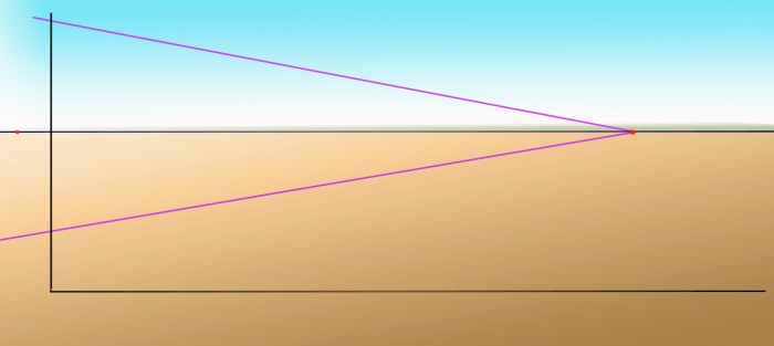
  3. Mark the VP and a new point, called the Measuring Point, just to the left or the right of the vertical scale.  The MP can be on either side, but it must be close to the vertical line.real4
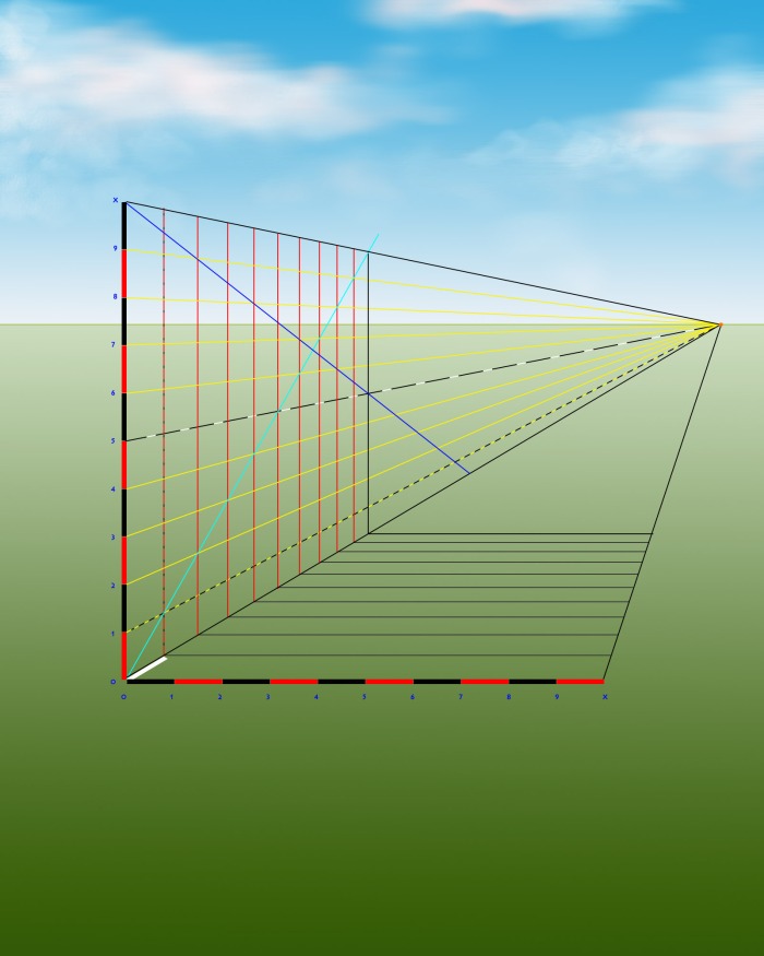
  4. Now, looking at the reference shot of Abu Simbel, one can see that there are 5 different sections in the sequence of Variable Spaces.  They are as follows:
    • Green Bracket: we will call these the FRAMES
    • Red Bracket:  we will call these the NICHES
    • White Bracket: we will call this the PORTICO
    • Purple Bracket: we will call these the JAMBS
    • Blue Bracket: we will call this the DOORWAY5spaces
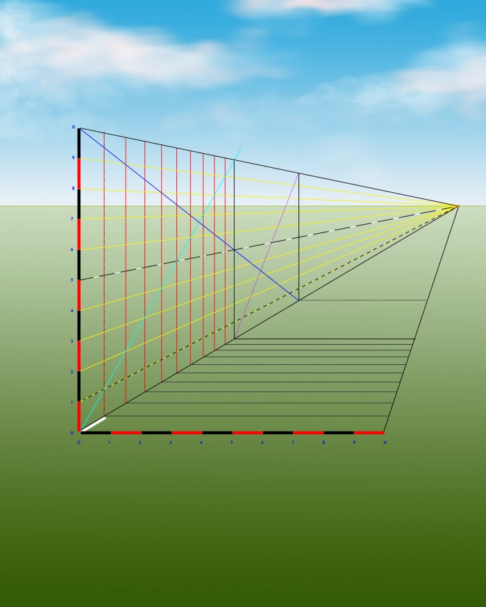
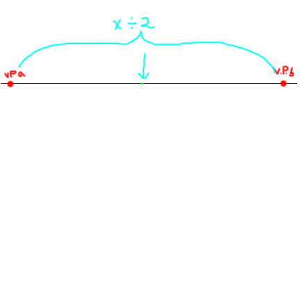
  5. Now, estimate the ratio of widths between the 5 spatial elements in the picture.  For simplicity, let us say that the Frames to Niches are a 1:2 ratio in width, and the Jambs to Frames are also 1:2.  (this means that the Niches are DOUBLE as wide as the Frames.  So too is the relationship between the Jambs to the Frames; the Frames are DOUBLE as wide as the Jambs).  Let us say the Jambs to the Doorway is 1:1.75.   Once you have established a ratio of the sizes by eye, decide upon a base unit for the Frames (since most of the ratios refer to these). We shall say the Frames are 2 cm.  Thus each section width is as follows:
    • Frames: 2cm
    • Niches: 4cm
    • Portico: 3.75cm (two jambs + doorway)
    • Jambs: 1cm
    • Doorway: 1.75cm
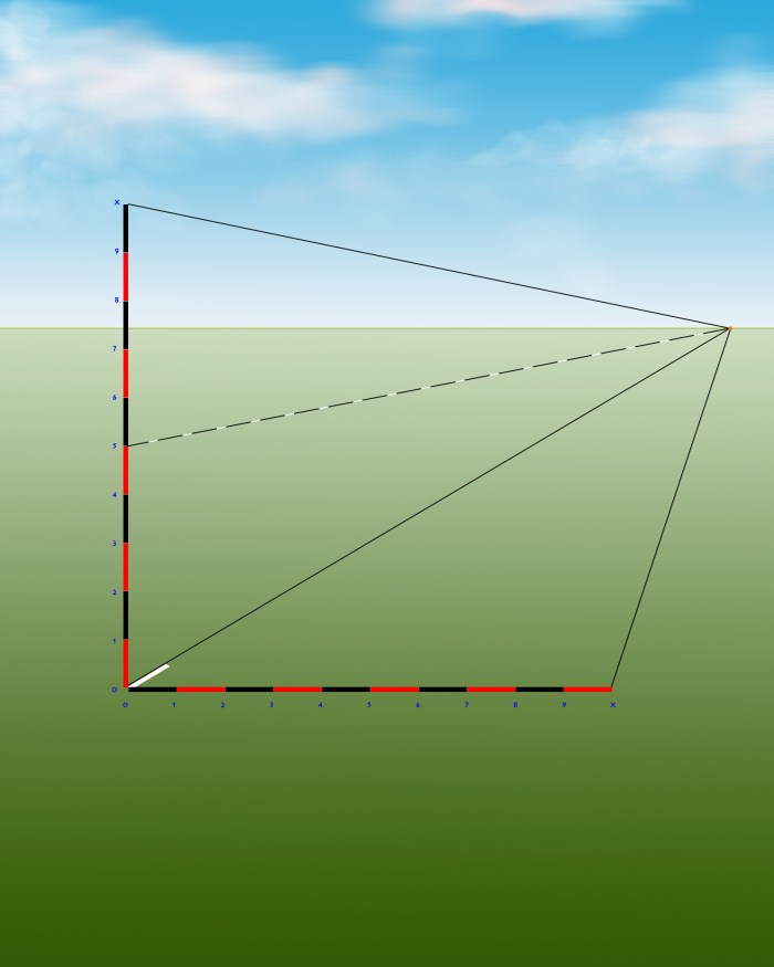
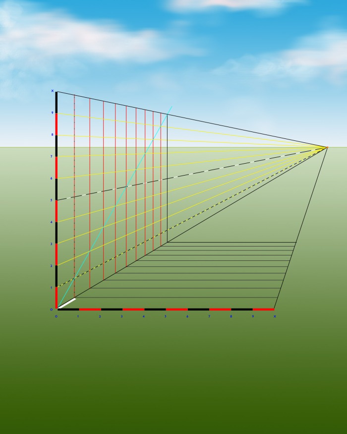
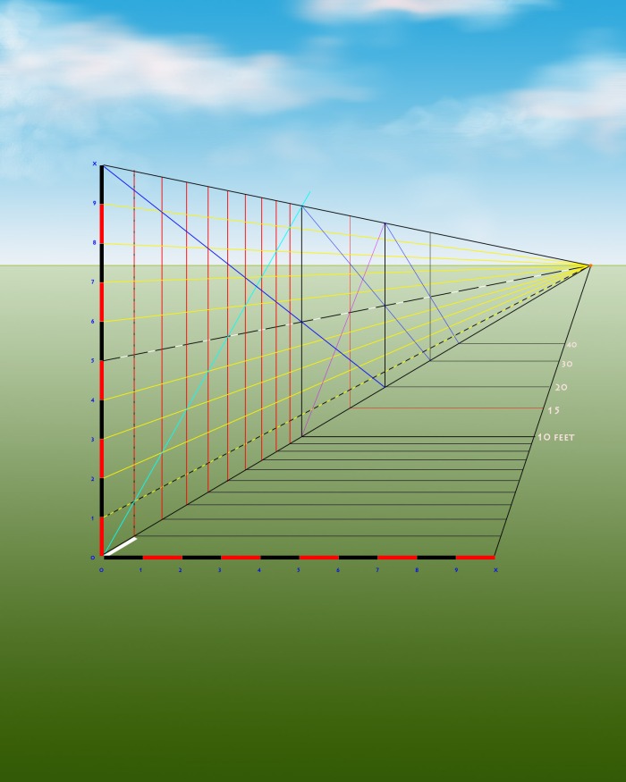
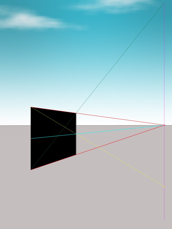
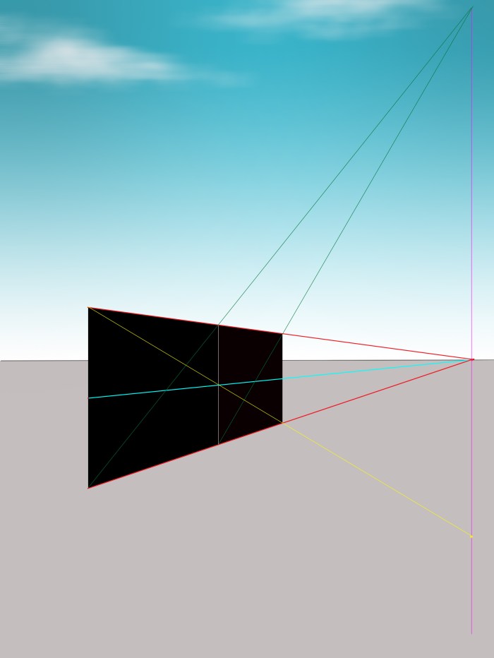
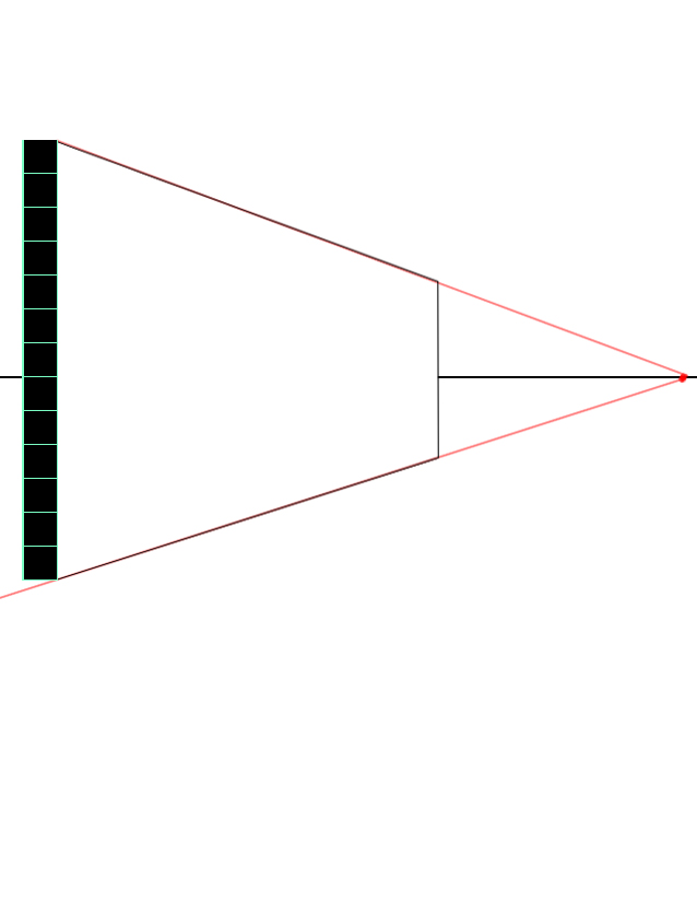
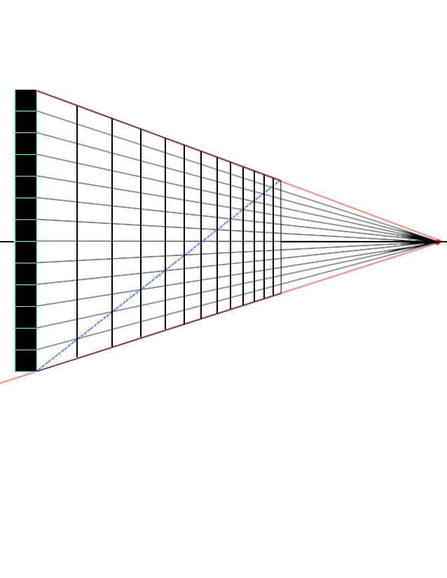
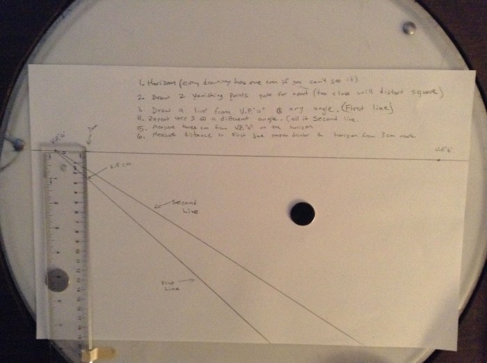
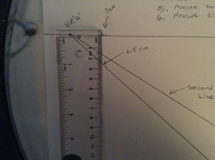
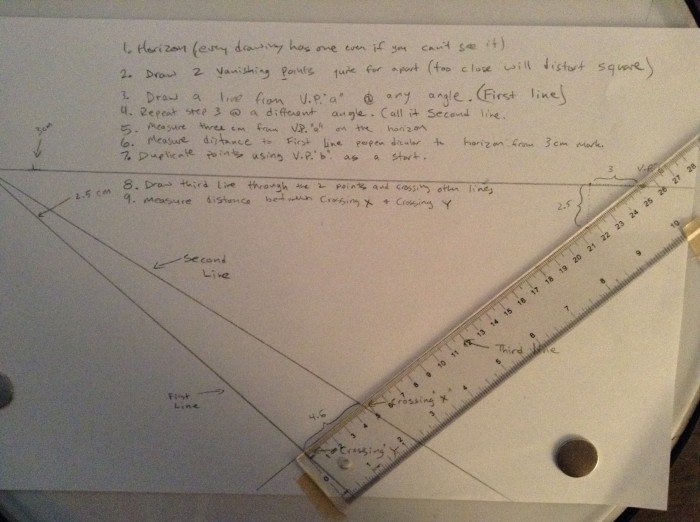
  6. Starting at the (0,0) point on the Vertical and Horizontal scale lines, lay out the measurements in the order that the sequence appears on the reference.  The full sequence is not measured in this example, in order to accommodate the size of the image, and readability.  In reality, one must layout the entire sequence on the horizontal Measuring Line.real5
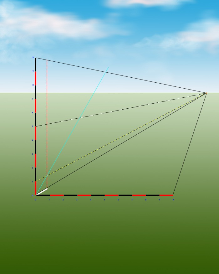
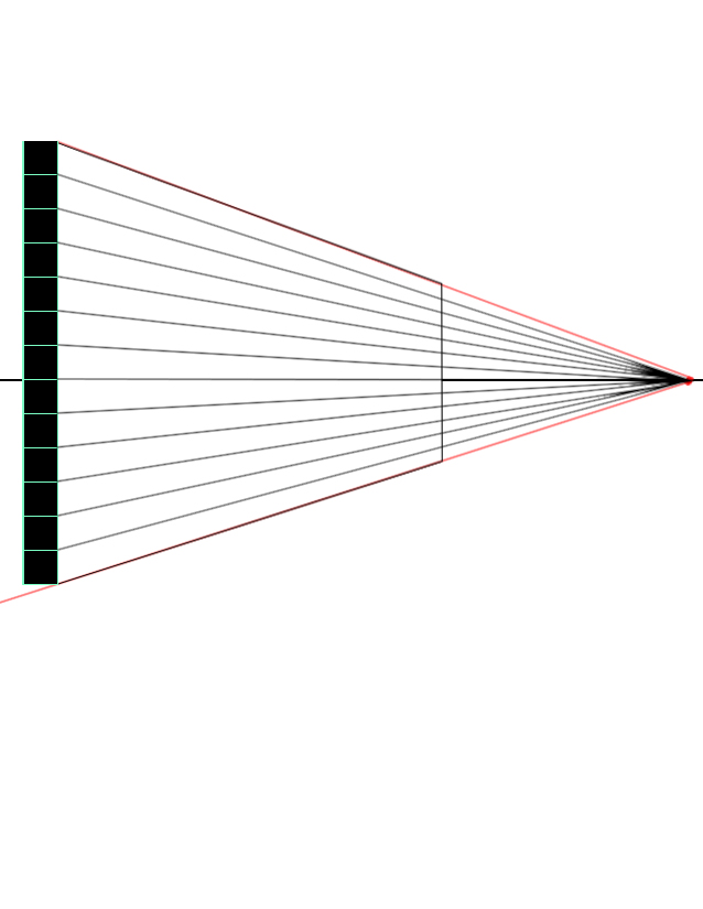
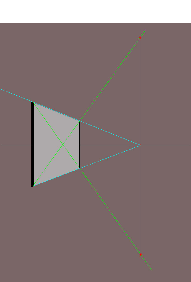
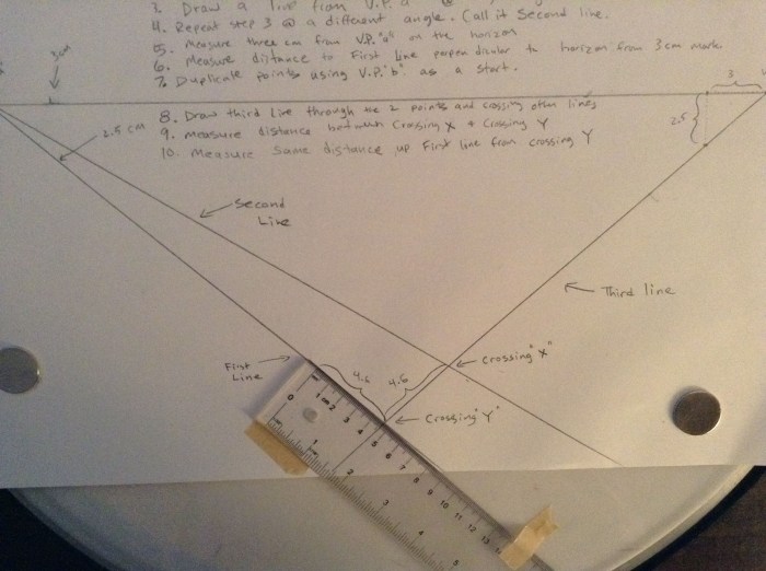
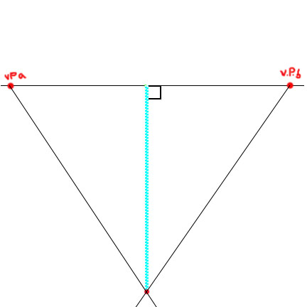
  7. Through the points on the Horizontal Measuring Line, cast new lines of measurement to the MP (Measuring Point)6real
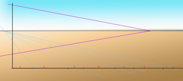
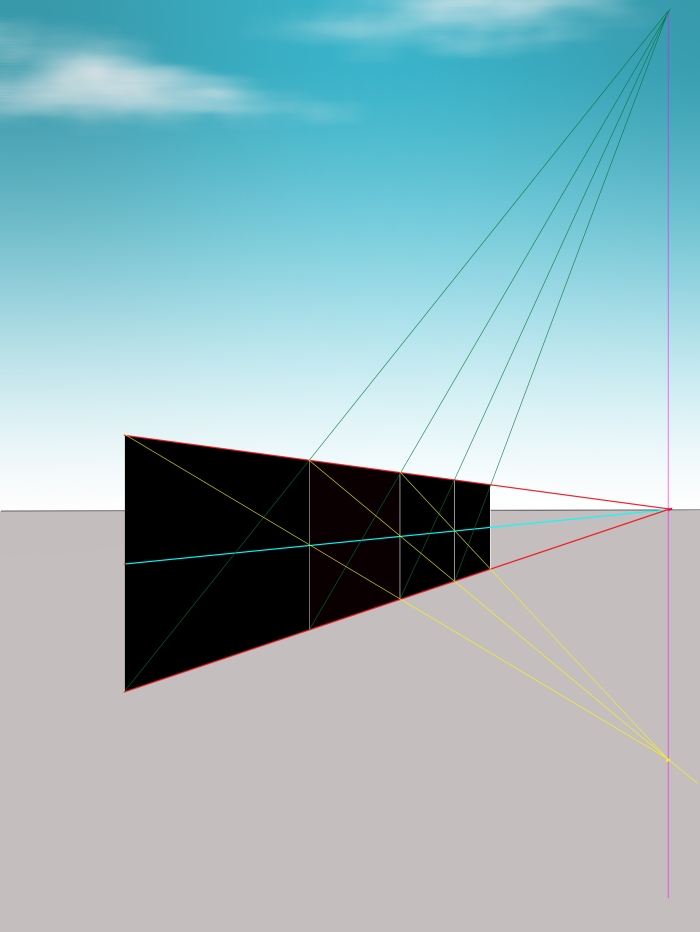
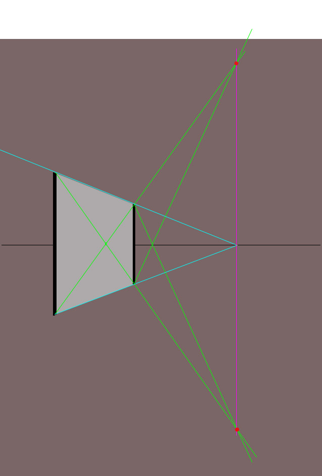
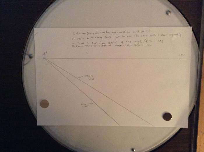
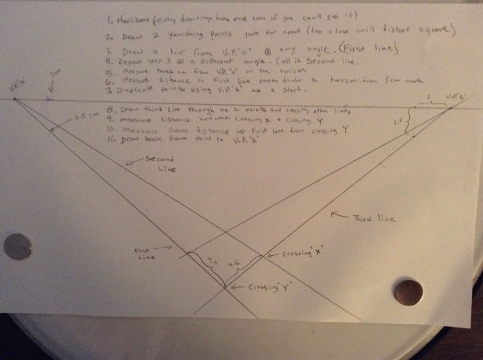
  8. The points where the cyan coloured Measuring Lines cross the bottom Perspectival Line will be the Variable Spaces on the monument, projected into perspective.  A secondary (red) line of perspective is cast to accommodate for the sloping nature of the temple’s face, i.e. it is not 90°. 8
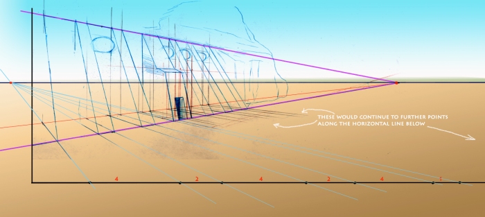
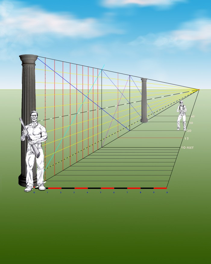
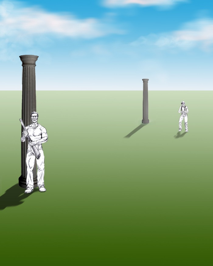
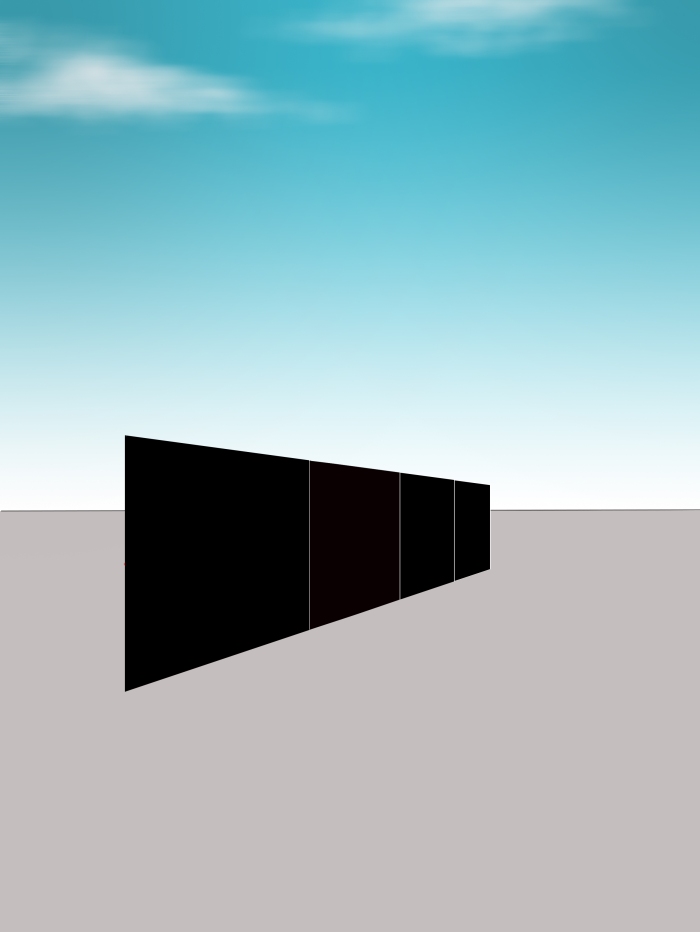
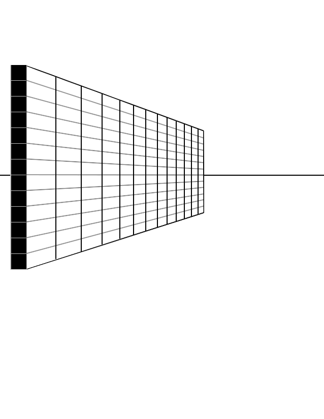
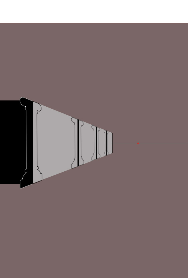
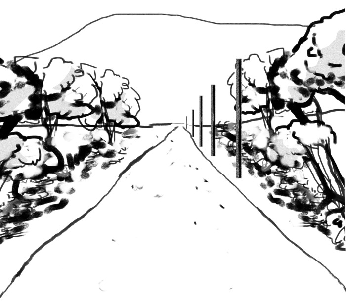
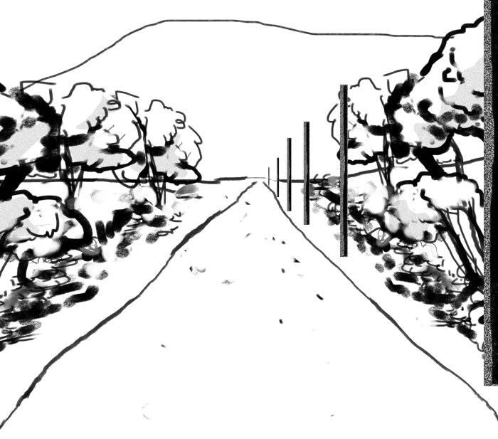
  9. Erase the guidelines and the new temple is drawn in the new perspective. Finish it to the level of detail that you desire.1inal

In closing, I would like to apologize for not posting this on Sunday as per usual.  I hope you are able to use this technique of projecting Variable Spaces within a Single Block.  I also hope to see you next week.

Drawing To Scale

It is amazing how much information Andrew Loomis packs into each of the pages of his books.  His method of instruction is to constantly expand the uses of techniques outlined on previous pages.  In so doing, he also expands the learner’s set of drawing mechanics in a straightforward way.  For example, on page 39 of Successful Drawing, the method of depth by diagonal is elaborated upon, and here Loomis shows the reader how to use the technique in order to execute a scale drawing.  He says:

Every artist should know how to draw to a scale.  Scale drawings require the division of vertical and horizontal planes into square feet or square units. 

Let us then examine the method.

  1. We must first establish a vertical and horizontal measuring line, like an X and Y axis, where the lines touch at right angles at point zero.  Both lines must have equal division of unit, which represent feet in the drawing. The size of the unit which you use is done by eye.  A horizon line is established and the measuring lines are placed upon the scene.1
  2. From each of the ends of the measuring lines, and from point zero, lines are drawn to the VP.  Set the VP where you want by eye.2
  3. Now, a fourth Line of Perspective is cast to the VP, this time from the mid point (at the 5) of the vertical line.  This line is represented as a black and white dotted line in the example below.  We shall call this line the Halfway Line.3
  4. Next, gauge by eye the optional depth of the first foot of measurement along the low Line of Perspective going from the zero point to the VP.  4
  5. When the first unit is established, cast a Line of Perspective from point one on the vertical scale (yellow checker in this sample), as well as a second vertical line at the point where the first unit terminates (red checker in this sample).  This first square unit will represent one foot. 5
  6. Ascending diagonally from the  low near corner (point 0, 0), cast a diagonal measurement line (cyan coloured in this sample). Make sure it crosses exactly through the upper furthest corner of the first square foot.6
  7. Where this diagonal measurement line (cyan coloured) crosses the top Line of Perspective, draw another vertical down to the bottom Line of Perspective.  This is 10 feet deep into the image from point 0,0.  Cast Lines of Perspective (yellow here) from each remaining vertical measurement points to the VP.  Where the  diagonal (cyan coloured) measurement line crosses the many interior Lines of Perspective (yellow), additional vertical lines are drawn.  These represent 1 foot sections receding into the distance.8
  8. Next, draw horizontal lines on the horizontal plane, each at 90 degrees from every incremental foot measurement determined in step 7.  This divides the ground plane also into ten 1-foot sections in perspective. 9
  9. As in last week’s posting, cast a descending diagonal line from the top near corner of the vertical plane, crossing through the far mid point delineated by the Halfway Line (black and white line) on the plane.  This shows where the next ten foot wide plane will terminate.  10
  10. Draw the vertical for the twenty foot mark, and then diagonally bisect this new plane, from corner to corner (purple diagonal in this sample).  Where that diagonal line crosses the Halfway Line is the centre of the second vertical plane.   12
  11. At the centre point where the newly drawn diagonal (purple diagonal in this) crosses the Halfway Line, draw a new vertical.  This will show the point of 15 feet in depth, as it is exactly between the 10 foot and 20 foot markers. 13
  12. Repeat this process of descending diagonals from upper near corner through the Halfway Line, and ascending from corner to corner to determine as much depth as needed.  Each line that descends from top corner through the Halfway Line shows us 10 more feet in depth.  15
  13. Now suppose we were asked to place these two men of different heights, on the field 20 feet away from each other.  Furthermore, we want to place two Greek columns of equal height also on the plain, 30 feet away from each other.  We want to place the tall black man beneath the near column, and the short white man 20 feet behind, and 9.5 feet over to the left of the black man .  The black man is 6 feet tall, the white man is 5 feet tall, and the columns are 10 feet tall.  Frontier
  14. With this method of Drawing to Scale, the task is simple.16
  15. Erase the guide lines and add some shadows, and the task is complete.  Notice how the short white man looks proportionately still like a short guy -even way back in the field.  Because the perspective is correct, and our Intelligent Perception is so fine tuned to seeing people in distances, we can tell he is a small man even though he is not standing directly beside any reference point.  This is the power of perspective.  17

Thank you for reading this week’s posting.  I hope you will subscribe and learn more about Andrew Loomis by keeping up with this blog.

A More Precise Method

Previously in Understanding Loomis, I have shown several ways of determining depth by diagonals.  The method explained today is another method of finding depth by diagonal, but this one is a more accurate method than those previously covered.  Today’s method should be used when the illustrator is seeking to draw to scale; i.e. when he must divide the vertical and horizontal planes into square units for measurement in perspective.  The previously outlined methods are fine when the illustrator is seeking to represent visually realistic perspective, but when mathematical precision is necessary -as in the cases of scale drawings-  a more precise method is needed.

Today’s post will explain the method of laying out the precise division of vertical planes.  How this is used in the creation of scale drawings will be covered in the next posting.

  1. First establish the horizon and the V.P. for the first plane.  Cast perspective lines back from the VP to establish the height of the plane.  Determine height by eye.2 precise
  2. Establish the First Unit depth also by eye. This establishes a Base Unit Plane, which will be cloned in perspective.  Next, cast a new line from the centre point on the nearest edge of the Base Unit Plane to the VP.  This will bisect the plane perfectly in half.  We shall call this new line the Middle Line. 3 precise
  3. When the first unit is established, it is cloned by using diagonals.  Create a Vertical Line by bisecting the horizon at the original VP.  Make certain to draw the Vertical Line long enough to accommodate the diagonals which you will draw in the next step.  4 precise
  4.  Cast the first diagonal (green in this example) from the near bottom corner through the far top corner to the Vertical Line (the pink line in this example).  At the place where the (green) diagonal line crosses the (pink) vertical, make a secondary VP5 precise
  5. This step is where the method tightens up the measurement.  Cast a downward diagonal (yellow in this example) from the top near corner of the plane, through the point where the bisecting Middle Line (from step 2) crosses the midpoint on the far edge of the plane.  This line does not go corner to corner. Extend this downward diagonal far enough for it to meet the (pink) Vertical Line.  Mark a tertiary VP at the low crossing point.  6 precise
  6. Again, as in step 4, cast a new ascending  diagonal from the next bottom corner (where the next plane will be) up to the secondary VP marked on the Vertical Line in step 4.7 precise
  7. Where the ascending diagonal (green) and the descending diagonal (yellow) both cross the original perspective lines (red), draw a vertical line to indicate the depth of the second plane.  This will be a more accurate representation of the First Unit Plane’s width in perspective, than that which was shown in previous postings. 8 precise
  8. Repeat the procedure by casting ascending lines corner to corner, and descending lines from corner through the Centre Line to establish the further planar depths. 9 precise
  9. Erase the guide lines to reveal the four planes receding into the distance, with more precise perspectival depth.10 precise

Conclusion

Readers will have noticed that with the introduction of a secondary guiding point, i.e. the bisecting Middle Line, the illusion of correct perspective is tightened.  For the sake of interest, compare the planes of today’s post with the divisions of depth created with the earlier methods in previous postings.  You will be able to see the subtle difference by eye, and how this method creates a more accurate representation of repeating planar depth in perspective.  This is especially true in the perspectival plane sections which are shown far off in distance.  The previous methods tend to shorten the depth incrementally, such that the distant planar sections become much too close together.

Next week, we will investigate how to use this method of depth by diagonal to set up for the creating of scale drawings.

A Specialized Method of using Diagonals

This week’s posting will be a very straight forward one.  Andrew Loomis’ third example in this section of Successful Drawing shows how the artist can use diagonals to create a checkerboard pattern in perspective.  This is useful for drawing repeating windows of uniform size, or bricks on a wall receding into the distance.  The example I will use is of a brick wall.

This is how it is done.

  1. Create the perspectival plane which will be the brick wall.  Locate the Vanishing Point. Use any angle that you wish.1
  2. Divide the near vertical edge of the wall into equal separations.  The size you choose will represent how tall each brick will be.2
  3. Cast lines to the V.P. from the points indicated by the vertical spacing you created with the brick heights in step 2.  We shall call these lines the Brick Height Lines.3
  4. Here is where the diagonal comes in.  Cast a diagonal line from corner to corner on the face of the wall you are drawing.  The diagonal can go up or down. 4
  5. Where the diagonal (blue line in this example) crosses each of the multiple Brick Height Lines, draw a 90 degree vertical from the bottom of the wall to its top.5
  6. Repeat this at each crossing point, and the wall plane will be divided perfectly in perspective.6
  7. Erase the guide lines to reveal the wall.7

Uses

This method can be used for drawing multiple series of drawers, such as in a morgue or a bank vault, architectural or vehicular designs, it can be used as a grid for aiding the placement lettering or imagery on signage, or as a way of drawing bricks and checkers.

The diagonal is the key to being able to measure the depth of the sections.  Next week, I will explain how the diagonal can help in measuring, and thus correctly drawing a repeating panel section in perspective.

Thanks for reading, and I hope to see you next posting.


Depth by Diagonals: method II

As discussed last week, the current section of the book Successful Drawing which I am reviewing, deals with some of the drafting rules for determining the depth of an object by casting diagonal lines.  Last week we covered the first method, and this posting then will explain Loomis’ second method which is outlined in the text.

The use of the bisecting vertical

This method is very similar to the one outlined in the previous posting, but here, Loomis introduces a few more ‘controls’ to make certain that the placement of receding points are accurate.  He advocates for the use of a bisecting vertical to be placed along the horizon line, to keep everything accurate.  I find this method to be very useful for drawing buildings, with repeating surface features, such as windows, facade details, or columns on ancient buildings.  Let’s get into it.

  1. First, let us consider that you are trying to draw a building, with a series of columns located in regular intervals along the side of it, going off into the distance.  First, create the near corner height of the plane you wish to decorate, and sight the V.P.per2
  2. Now, the artist must place the ending of the facade plane at what Loomis calls the optional depth.  This is the most unscientific part of his instruction, because it leaves the artist to place the second line by eyeball.  He uses the word optional not in the sense that one may draw it or not draw it, but instead Loomis means where the line is drawn is optional, i.e. it is up to you.  Once the visual depth chosen pleases the artist’s eye, he has created a section. The second line drawn is called the Terminus Line, as it delineates where the section terminates.  This section is now easily cloned in perspective.per3
  3. Now, the next step is the technical part of the procedure.  The artist casts lines diagonally through the section, starting at the near top and bottom corners and extending through their diagonally opposing corners. Following that, a vertical line must be drawn bisecting the horizon perpendicularly, through the V.P.  The diagonal lines must extend far enough to reach the point where the new vertical line delineates.  Mark the points where the diagonals cross the vertical.  Let us call the new high and low points, the Vertical Points.per6
  4. This X of diagonal lines shows the centre of the section, and sets the artist up to clone the depth for the following section.per7
  5. To find the depth of the second section, the artist again casts new diagonals, but this time he must start from the top and bottom of the newly drawn Terminus Line of the established section.  These lines are cast diagonally up and down to both the high and low Vertical Points,  This will create another X within the Lines of Perspective.  per9
  6. A new Terminus Line is drawn vertically where the diagonals cross the Perspective Lines, and a second section is established.per10
  7. Repeat from step 5, casting diagonals to the Vertical Points.  The sections will be drawn in their proper visual depth as per the laws of perspective. per11
  8. These sections could delineate where a repeating surface feature is found on a building, such as a column or any regular repeating element, including doors, windows and other architectural features.  This method is even useful for drawing a series of parked cars along the sidewalk, since many cars are relatively the same length, the sections can represent the cars’ body length.  Any anomalies of vehicular type can be adjusted for as needed. per12

This concludes our posting of Understanding Loomis.  Next week’s post will again unpack another of Andrew Loomis’ methods of finding depth by diagonals.  Stay tuned.

Finding Equal Spacing using Diagonals

In this posting of Understanding Loomis, I will explain the primary method Andrew Loomis outlines in what he calls ‘depth by diagonals’.  This is a rule of drafting which accurately represents depth in a subject matter featuring a repeated pattern, or a repeated spacing of surface feature.  This particular treatment is useful for illustrating a sidewalk receding into the distance, or a tiled floor going off down a hall, or a train track with ties crossing the rails, traveling away to a vanishing point.  It is a very useful mechanic to know.

To emphasize why knowing this mechanic of perspective is important, I will describe a scenario where such knowledge would save the artist painstaking hours of ineffective trial and error, or unconvincing guesswork.  Consider; you as an illustrator have been given the task of drawing a rural road, where small trees and shrubs are growing along the side. Also standing along the road at regular intervals of 30 feet, are a series of 6 telephone poles on the shoulder.  The image is to be drawn with the vanishing point of the road in the centre of the horizon, as if the viewer were standing at the head of the road, looking off to where it fades into the distance.

Drawing the simple one-point perspective of the road is no problem, and the shrubs/trees needn’t be precisely drawn on account of their being organic and irregular in nature, hence their placement is not a problem either.  The telephone poles on the other hand are man-made, and erected with a constant distance of 30 feet between each of the pole bases.  To be able to accurately place each pole as they recede into distance, is a baffling task to those unaware of technical perspective.  Many artists would rely of approximate placement of the poles, by ‘eye-balling’ the spacing.  This may be acceptable in some cases, but where approximation is not acceptable, a technical solution is necessary.

This then is how it is done.

Depth by Diagonal

(For the sake of these perspective lessons, crude sample drawings which were done in Photoshop in a matter of a few seconds, will be used forthwith.  Proper, elegant drawings will be used as examples where actual drawing matters are being considered)
  1. First represent the road and the bushes in one point perspective.  Bushes and trees are organic, and can be represented by eye without difficulty.  The rules of perspective still apply, but the artist can be a little sloppy in representing their relative size, since trees and shrubs are not regular.road1
  2. Next place your first pole.  Use the relative size of the trees around it for its height. road2
  3. Next find the Vanishing point of the road on the horizon line.road3
  4.  Now, draw a diagonal line from the near corner of one of the Lines of Perspective, through the base of the first pole to a secondary point on the horizon line. Let us call this new point on the horizon Point One. road5
  5. Next, draw a horizontal line (i.e. parallel to the horizon line – natch!) from the base of the pole, crossing through both Lines of Perspective.road6
  6. From where this horizontal line meets the opposite Line of Perspective, draw another diagonal line to the secondary point you drew in step 4, which we called Point One.road7
  7. Cast lines to the actual VP from the top and bottom of the telephone pole, and pay attention to where the bottom line crosses the diagonal which you drew in step six.road8
  8. At the crossing point, draw your second telephone pole.  The top line will show you how tall to make it.  road9
  9. Repeat the process, and erase your guidelines.  The end result will show the poles moving off in correct perspective, spaced evenly apart.  road10
  10. Work in reverse  to fill in any posts which should appear before the initial one you drew.road11

The Uses of  Depth by Diagonal

Shown below is a sample of the nuts and bolts of the Depth by Diagonal mechanic.  This example is shown stripped of any context in order to help the student imagine the uses of this rule of perspective.  Some ways I have used this method of representing perspective in drawing comics are as follows:

  • representing regular sized plates of steel, clad on the hull of a ship
  • drawing the separation lines of ceiling panels on a t-bar drop-ceiling in an office
  • sidewalks, with contraction joints showing in the concrete
  • patterned carpet expanses
  • windows, or other architectural features on buildings
  • any regularly spaced series of object, such as telephone poles, the cars of a train, the ties between train track rails, the broken lines on a road which indicate a passing lane etc.

dbydiagonal

Next week, we will examine a variation on this method of finding Depth by Diagonals.  I hope you will join me.

Imagining the Geometric Shape

Previously, I went at some lengths to explain a concrete method of drawing a laying square at any perspective.  The reason this was done was in order to establish a groundwork for the student to begin to visualize the square as the base of a cube. A cube can me made from the laying square by drawing vertical lines up from the corners, and by adding an identical laying square as the lid.  Alter the height and width dimensions, and one can easily draw various Rectangular Prisms in perspective.

The Rectangular Prism in 3-Dimensional space is the primary shape Loomis encourages us to become familiar with from any angle.  The reason being, is that this shape will enclose any other shape which exists. Even the perfect sphere will fit in the perfect cube.  Some shapes are long, some tall, many are irregular; but when one visualizes a Rectangular Prism bounding what one is trying to draw around the object, the artist takes the first step to being able to draw that object with mass and perspective.

If one does not use a beginning framework of Rectangular Prisms to work out the perspective of the various objects within a composition,  the shortcomings will be evident to viewers on account of, again, ‘Intelligent Perception’.  Stated differently, there is no way to “fake” correct perspective, so it does one best to work it out properly at the beginning.

Setting up a a geometric shape as a shorthand for an organic shaped object has further uses beyond perspective and understanding mass.  An additional use is in aid of the artist seeking to establish values.  When an artist is trying to work out his values (lights and darks) within a picture, it is much easier -and more appealing visually- if the gradation of light to dark is done in a series of planes, rather than rendered as one continuous blend.  The ability to see form as a series of interconnected geometric shapes is essential to rendering transition of values in planes.  This treatment of light and dark creates an aesthetic which the photograph cannot duplicate, and thus, it remains the domain of visual artists.

male-9
The Male Figure rendered in planes

Drawing the ‘Laying Square’

Technical Perspective Continued

Last posting quickly outlined the principles of one point perspective.  The key points included:

  1. Every picture has a horizon
  2. An object’s relationship to the horizon creates the illusion of a perspectival view of the scene to the viewer
  3. The vanishing point is the point where a viewer’s sight is limited to

The previous posting used a simplified fir tree as the subject.  It is true that every picture has a horizon and involves the vanishing point, but it must be mentioned that natural phenomena, such as mountains, rivers, trees and bushes, are all very forgiving regarding perspective.  These forms are organic and do not involve straight lines, and furthermore, viewers will accept a very wide range of sizes and shapes in their representation.  This aspect of the inanimate, natural phenomena makes landscape painting and drawing much easier than works which involve architecture, humans or animals.  Traditionally, landscape painting has been considered the third lowest form of painting on account of the relative simplicity of the pursuit.

This posting will outline the fundamentals which lead to understanding how to draw geometric shapes in perspective.

As mentioned before, the initial step to drawing a geometric shape in perspective is mastering the ability to draw a perfect square, appearing as if it were laying flat on an imaginary surface.  This challenge is essential for revealing how an artist begins to create the illusion of space within a drawing.

Andrew Loomis does not break this task down for us, and many artists will be able to do this, merely with their eyes.  I personally find it very easy to draw a perfect square laying on an illusionary ground on any angle.  This is because I can visualize the correct placement and degree of the angles from the years of experience which I have integrated.

For the sake of the artists who do not find this easy, I have devised a simple method of finding the correct angles needed to draw a laying square from any position of perspective.

The Lesson

  • Draw a horizon, and keep it towards the top third of your paper.  Every drawing has a horizon.  perspective 1.jpg


  • This time, we will use 2 Vanishing Points.  Place them far apart.  Putting the V.P.’s too close together will create distortions in your perfect laying square.  The left hand V.P. will be “a”, the right hand V.P. will be “b”.perspective 2.jpg


  • Now, we draw a line at any angle from V.P. ‘a’, such that it crosses an imagined point between your two V.P.’s.  This line we will call the First Line.

perspective 3.jpg


  • Now we will repeat the previous step, but this time using a different angle of trajectory.  We will call this line, Second Line.perspective 4.jpg


  • Now, for the next step, we measure 3cm from V.P. ‘a’, down the horizon line.  This point we lightly mark for reference.perspective 5.jpg


  • Using the 3cm mark as the starting point, measure the distance to the First Line, in a perpendicular to the horizon.  This will create a right triangle between the horizon, the First Line and the perpendicular measured.  In my drawing, the distance happens to be 2.5 cm.  This is not a set measurement, and it will always be different depending on the angle which the First Line was drawn at.perspective 7.jpg

perspective 8.jpg


  • The next step is to duplicate those points with exact measurements starting with V.P. ‘b’.  This will create an equal, but reversed right triangle with V.P. ‘b’ as the first vertex. perspective 9.jpg


  • From V.P. ‘b’, draw the Third Line, using the newly drawn low vertex point as the angular guide. Draw this Third Line such that it crosses through the First and Second Lines.  The crossing points with the First and Second Lines we will call Crossing ‘x’ and Crossing ‘y’. perspective 10.jpg


  • Measure the distance between Crossing ‘x’ and Crossing ‘y’.  My drawing happens to be 4.6 cm.  This measurement is relative to the angles of the First and Third lines, and is therefore not a constant measurement.perspective 11.jpg


  • Now, we measure that same distance up the First Line, from Crossing ‘y’, towards V.P. ‘a’.  Mark the point.  Again, my measurement of 4.6 cm is particular to my drawing.perspective 12.jpg


  • Draw Fourth Line back from that point to V.P. ‘b’ to complete the perfect laying square.

perspective 13.jpg


A Quick Way

There is a quick way to skip essentially from step 2 to step 8, but it involves having a tool with a set 90 degree to trace from (such as a drafting triangle or a t-square).  I will outline it here for those with such tools.

  •  Draw horizon.  Choose vanishing points

quick 1.jpg

  • Measure length between the two V.P.’s, and half that number.  Measure that distance  over from one of the V.P.’s to find the mid point between them.

quick 2.jpg

  • Drop a 90 degree line down from the centre point, perpendicular to the horizon. Call this point the Centre Vertexquick 3.jpg
  • Draw First and Third Lines from that point to either V.P.’s.quick 4.jpg


Drawing the Second and Fourth lines will work the same way if you choose a point above or below the Centre Vertex to create different angles.

Conclusion

Now with a laying perfect square in perspective, it is a simple thing to draw the perfect cube from the groundwork we have lain.   We will complete this 3 Dimensional cube in the next posting.


Perspective


Andrew Loomis preface

The books Andrew Loomis wrote are wonderful summations of his knowledge and his ideas.  They are also the preeminent folios of his beautiful drawings.  To hear my assessment of these collections, one might wonder why there is a need to author a blog entitled “Understanding Loomis”.  Let it be said then, that as an advocate for clear thinking and clear instruction, I believe that despite the quality of his books there still is room to finesse Andrew Loomis’ pedagogical methods.  Perhaps I am more slow-witted than others, but in several cases within the breadth of reading his writing, I was only able to grasp his point by carefully reading the text, drawing the exercise/example, then reading his text again.  The point being that reading his words and observing the pictures only constituted a very cursory understanding of his theory for me; I needed to break it down further to integrate the truth he is expressing.  To explain the theory and technique in written form for a third party helps clarify Loomis’ thoughts even more in my mind.  This then is the continued reason behind the project and my desire for fully “Understanding Loomis”.  In addition, I hope to illuminate my readers to the beauty of his reasoning mind, and the technical solutions he has outlined to achieve Successful Drawing.

Theory of Perspective, pages 20-29

(notes were originally taken by myself on Jan 7th, 2016)

The first major idea that Andrew Loomis covers is the common idea that everything we see and seek to draw can be broken down into geometric shapes; the block, the cone, the pyramid, the cylinder, the sphere and the torus.

(for those unfamiliar with the final shape called the torus, here is an image of one)

Simple_Torus.svg.png

He further expands this point by showing how the various and complicated forms  in nature are really only elaborations of the overarching basic shape, the block.  It is important to recognize that Loomis does not call the primary shape the cube -his term ‘block’ constitutes cubes as well as rectangular prisms of all shapes; it is a more basal term.  He adds that a block is to be considered the main shape because even a perfect sphere fits within a cubular block, thus the block form can be used as a shorthand for all the others.  He states: ” The cube or block may be thought of as the box that will fit around anything in the universe.”

This is where Loomis really gets cooking.  Following this point, he goes on to aim at the heart of one of the most trouble-inducing elements of drawing,  figure ground relationship with relative proportion.

Loomis confidently states that the challenge is actually one which is easily met, even though many experienced illustrators and artists fail to achieve it.  Furthermore, when one considers Loomis’ theory of “Intelligent Perception”, the fact that everyman can plainly see an error in figure/ground relationship, a need to sort this problem out shows as a paramount concern.

Following this he indicates that using the geometric shape as a starting point is more than a method of establishing form, it is also an essential way to comprehend how light and shadow effects form. Using geometric shapes establishes an understandable mass to the subject in our mind, so we are commonly able to visualize the back and the sides of the subject which are hidden from view.

The way which light falls on the geometric shapes is predictable and simple to memorize.  There is a Truth in the correct modelling of light and shadow on a shape which ‘Intelligent Perception’ knows.  The modelling reenforces the form, as each are interchangeable partners; form and modelling, modelling and form.

On the other hand, the absence of correct modelling (and therefore the absence of correct form) presents a problem so profound that no amount of technical panache or random hatching and texturing can correct it.  In this Loomis is in agreement with another favourite illustrator of mine, John Buscema.

I have read somewhere Buscema stating that other comic artists who added unnecessary lines and creases on a face were in fact attempting to make up for an incorrect placement of the features, a basic mistake which they couldn’t recognize.  In your own personal study of art, and especially drawing, I encourage you to look out for this.  When your ‘Intelligent Perception’ alarm is going off, take a quick look to see if the drawing is overly cluttered with detail.  An ‘open’ drawing has nothing to hide behind, and when the artist simply places the features correctly, the viewer will be satisfied.


Understanding Loomis

Meet Andrew Loomis, illustrator

My favourite drawing instructor and artist in general is Andrew Loomis.  He was an American illustrator who worked at the tail end of the Golden Era of illustration.  His contribution of elegant illustrations were used in commercial ads, book covers and magazines, but he was also a highly respected instructor of art during his career.  The observations and facts about technical illustration and drawing which Loomis made throughout his career were collected in a series of books  from 1939 to 1961.  These books cover every facet of illustration theory and technique.

The books themselves are indespensible resources and should be owned individually, but that being said I might add that some of the concepts within the breadth of the works are difficult to integrate for general readers as well as for students of art.  Thus, to help clarify these essential concepts of drawing, I have endeavoured to develop this blog which I have entitled Understanding Loomis.

My purpose is twofold here, the lesser of which is to generate a companion piece to Loomis’ writing for other artists to read at any level.  The primary purpose of this blog is for my own study, so that I may come to fully integrate the concepts which Loomis is explaining in his books within my own mind.

Successful Drawing

51J8sR5Z6DL._SX361_BO1,204,203,200_

I will begin the systematic review and breakdown of Andrew Loomis’ writing with the late-entry publication entitled Successful Drawing, from 1951This book appeared chronologically near the end of Loomis’ career, and although he started coalescing his concepts and discoveries into book format at the end of the 30’s, Successful Drawing is a good place to begin.  This title was re-released in a slightly altered form in 1961 as Three-Dimensional Drawing.

The reason I will begin here is that I have found Successful Drawing to have the best balance between drawing fundamentals and art theory.  It should be said at this point that readers will find art theory to be more emphasized within the writing of Andrew Loomis than is commonly found in most other instructional works.  The principle which Loomis takes as a starting point is that there is no division between theory and practice, and that to harbour a vague understanding, or a contradictory theory of art will only lead an artist into struggles which should have been avoidable.

The sense of life he has is positive, objective and technical to the point of mathematic.  I find this approach to be a very, very welcome panacea to the confused mindset of artists steeped in Fine Art-school ideology and those unquantifiable art theories which place their emphasis on expression, creativity and “meaning”.  Loomis focuses on the tangible and mechanical elements  of art which -as he promises- can be learned, and will yield a correct representation of reality.  This is most valuable in that these are terms which an artist can control and can learn through attentive practice.

Next posting I will commence with the actual breakdown of Loomis’ writing, where we will begin with his outline of the fundamentals needed to start on the journey toward Successful Drawing. 

I hope that you can join me.  In the mean time, enjoy these samples from Andrew Loomis.